Gradient Background Image
 

Tech Matters

TECH MATTERSbailey Metal Processing Limited - Products


  • I-Units – A Standard for Determining Flatness

    by Esther Mar | Aug 29, 2018

    Flatness can be a confusing subject.  People know when they see a shape condition that will give them trouble but they sometimes don’t describe it accurately and often don’t specify their requirement in a meaningful way.  The industry uses terms such as commercial flat, half standard, flatness critical, restricted flatness or panel flat but these terms are vague.  ASTM standard specifications contain flatness tolerances that are only based on maximum deviation from a horizontal flat surface, although they do refer to two alternative methods for flatness determination, I-Units and % Steepness, contained in ASTM A1030.

    I-Units is an exacting quantitative flatness measurement.  It is a dimensionless number that incorporates both the height (H) and peak to peak length (L, or P in the diagram below) of a repeating wave.

    iunits

    The formula for I-Units is as follows:        

    I = [(3.1415 x H)/2L]2 x 10

    Simplified, I = 2.467[H/L]2 x 105

    For example:  a sheet with a 1/16” high wave which repeats every 12” would have an I-Unit value of 6.7.

    There are several charts on the internet that provide the calculated values for a given H and L.


  • Mils vs. Microns

    by Esther Mar | Aug 22, 2018

    milsvsmicrons

    Mil -
    A unit of measurement in the English system that is measured in thousandths of an inch.

    (i.e., .001″ = one thousandth of an inch or 1.0 mil)


    Micron - A unit of measurement in the metric system that is equal to one thousandth of a millimeter.

    (also called a micrometer, abbreviated ‘μm’)


    For the conversion:

    Mils to Microns: (Number of Mils) x 25.4 (i.e., 0.75 mil = 19 microns)

    Microns to Mils: (Number of Microns) / 25.4 (i.e., 14 microns = .55 mil)


  • Transit Abrasion on Galvanized Sheet

    by Esther Mar | Jul 05, 2018

    Galvanized sheet sometimes exhibits a surface imperfection that appears as short black marks, usually in patches.  This condition has several names in addition to transit abrasion including fretting corrosion, friction oxidation, wear oxidation and chafing.  These terms refer to the root cause of the problem, which is related to friction between contact points, similar to galling. The condition is characterized by a mirror image on the reverse side of the sheet. The reason the term corrosion or oxidation is used is that this imperfection is associated with the buildup of oxide particles.

    Fretting corrosion is the most technical name.  It refers to corrosion damage at the high points of contact surfaces.  It occurs under load, under conditions of repeated relative motion of the surfaces in contact with each other, and these two conditions must be sufficient to produce deformation of the surface, which is likely with galvanized sheet because the zinc coating is fairly soft. This mechanism can affect any two surfaces that are not intended to move against each other and, in the case of machinery, can prematurely wear out parts.

    Fretting corrosion has been observed on galvanized steel in both coil form and bundles of cut lengths.  This condition is never seen on the galvanizing line, almost always being found in a customer’s plant.  The repeated motion comes from vibrations that occur during shipment of the product.  The condition is rare in the case of truck shipments, generally being prevalent when product is transported by train and ship where it incurs vibrations for long periods of time. The load comes from the weight of the coil (or stack of sheets).  This is why transit abrasion is observed mostly on the outer portion of the coil at the bottom half of it (or bottom portion of the bundle).

    There are measures that can prevent or minimize transit abrasion, all targeting reducing load or minimizing friction.  Actions that are very effective are designing support saddles to reduce concentrated point loading on the bottom of coils and avoiding stacking during transit.  Other measures are reducing the coil size and oiling the material, although these methods are not always practical or possible.

    There are two mechanisms that operate to produce fretting corrosion:  wear-oxidation and oxidation-wear. The first proposes that cold welding occurs at the contact points with small fragments of metal being removed and that these immediately oxidize.  The second proposes that the normal oxide layer already present on the galvanized sheet is ruptured at the high points under load and vibration, thus producing oxide particles. 

    Fretting corrosion is a cosmetic condition. There is no evidence that it is detrimental to the corrosion resistance of the galvanized sheet.

    transit1

    transit2

  • Thickness Expectations in Sheet Products

    by Esther Mar | Jun 22, 2018

    There is a book I am hoping to locate and read called “Ribbon of Fire” by Jonathan Aylen and Ruggero Ranieri.  Abstracts say that it reviews economic and technological developments showing how the wide hot strip mill evolved in the USA from narrow (3” max) hot strip mills rolling ‘hoop’ in the 19th century, through 4” mills rolling ‘skelp’ to 7” wide mills rolling 100’ lengths by 1890.  Widths and lengths rolled slowly progressed - 24” wide and 500 – 1000’ long - and then a breakthrough was made in 1923 by an engineer at Armco and in January 1924 the first 36” wide hot strip was rolled in the multi stand mill in the Middletown Works, in Ohio.  This was rapidly followed by an improved 36” mill at the Columbia Steel Co. at Butler Pennsylvania, which soon was widened to 48”.  The main innovation of this mill was a four high finishing stand using a small diameter work roll supported by a larger back up roll, this enabling greater reduction between passes.  It is from this mill design that all future wide hot strip mills developed. 

    From the technology of the four high mill stand stems the understanding of gauge performance of sheet products.  I say “sheet products” because as the product range of these mills increased, governing bodies differentiated between “sheet” and “strip”, the latter being rolled in narrow mills.  For example, ASTM A568 (Steel, Sheet, Carbon, Structural and High-Strength, Low-Alloy, Hot-Rolled and Cold-Rolled, General Requirement for) classifies “hot rolled strip” as material with mill edges 12” and less in width.  “Hot rolled sheet” is further reduced in wide cold reduction mills to produce “cold rolled sheet”.  But “cold rolled strip” is rolled in “strip mills” that are narrow cold mills.  The raw material for it is generally “hot rolled sheet” that has been pickled and slit into narrow widths.  The end product has thickness variation which is less than sheet mill industry tolerances and is often produced to custom characteristics.

    The following text deals with thickness variation in hot rolled and cold rolled sheet but uses the term “strip” because it is the commonly used terminology in the trade.

    The process of creating a finished flat rolled product from a slab consists of several stages.  These stages in a typical hot rolling mill are: reheating the slab, roughing, finishing, measuring, cooling, and coiling. As the hot steel travels through the process its thickness is successively reduced in the various mill stands. 

     thickness1

    The finishing process gives the strip its final dimensions.  The strip thickness (and flatness) is measured in real time by X-Ray gauges at the exit of the finishing stands.  Measuring the final dimensions of the strip is critical for the mill controllers as they adjust the mill parameters in real time with feedback from the gauges to minimize variation in thickness (and shape).

    The concept of the mill stand mentioned at the end of the first paragraph is shown below. A stand like this is several stories high. It is composed of  a set of work rolls between which the strip passes, a set of backup rolls, which are bigger, and actuators to control the gap and the bending of the rolls, all supported by a frame.
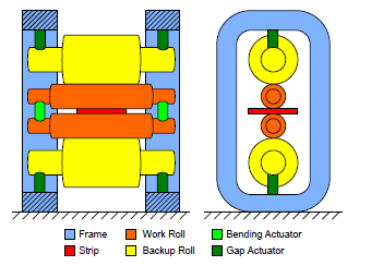
    thickness2

    Rolls consist of two parts:  barrel and neck.  The barrel is the part of the roll that comes into contact with the strip or another roll.  The neck is the thinner portion of the roll, part of which rests in a bearing.  The bearing is held by a chock which is connected to the stand frame.  As the hot strip travels through the stands there is force on the rolls which causes their deflection and resulting strip deformation.  This force, as well as other factors (including roll thermal profile, roll wear, strip width) affects the cross width dimensions of the strip.  The resulting cross section of the strip looks as in the schematic below.
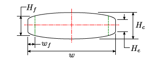
    thickness3

    Most mills refer to the overall cross width configuration as the “profile” which is composed of the edge drop off, or feather, and the crown.  The crown is the difference in thickness between the thickness at the centre of the strip and the thickness at the end of the edge drop off, or feather (usually about 2” in from the mill edge). 

    The profile of the strip is generally consistent from the lead end of the coil to the trail end of the coil although it can vary towards the coil ends.  Separately, there are methods in modern hot strip mills that are used to control the shape of the strip (both in terms of flatness and crown).  These include:  roll bending, roll shifting, and inflating roll (variable crown roll).

    When hot rolled strip is cold reduced the aspect ratio of the hot strip profile is maintained but the magnitude is proportionally smaller in the cold rolled product.

    The following table from ASTM A568/A568M – 13a provides the tolerances for hot rolled sheet steel.  The tolerances include variation along the coil length and across the coil width.  The variation attributable to the profile can be in the order of 1 – 5% of the average thickness depending on a variety of factors.
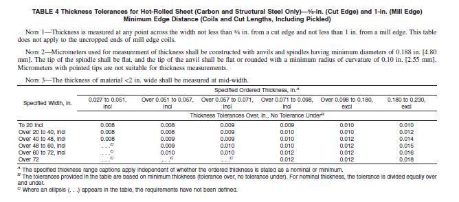
    thickness4

  • Fabulous Websites

    by Esther Mar | Apr 05, 2018

    internet icon

    Some readers may not be aware that there are a variety of excellent resources on line that provide extensive technical information.  The following are very useful and most of the information is free:

    • www.galvanizeit.org – this is the website of the American Galvanizers Association
    • www.galvinfo.com – this is the website for a program of the International Zinc Association (www.zinc.org)
    • www.aist.org – this is the website for the Association for Iron & Steel Technology
    • www.cssbi.ca – this is the website for the Canadian Sheet Steel Building Institute