Gradient Background Image
 

Tech Matters

TECH MATTERSbailey Metal Processing Limited - Products


  • Preventing Corrosion

    by Esther Mar | Jan 28, 2020

    In the presence of water most metals corrode:  iron and steel rust, galvanized steel forms “white rust” when the zinc coating is exposed to moisture in the absence of air, copper turns green, and aluminum will stain under certain conditions.  Sources of moisture can be external (obvious sources such as precipitation and water leaks) or related to humidity causing condensation.

    Humidity is a measure of the amount of water vapour in the air.  Specific humidity is expressed as grams of water vapour per kilogram of air.  In the atmosphere the ratio can vary from nearly zero (in deserts or polar regions) to as much as 30 grams per kilogram (in warm, tropical climates).

    Relative humidity, expressed as a percent, also measures water vapour, but relative to the temperature of the air.  In other words, it is a measure of the actual amount of water vapour in the air compared to the total amount of water vapour that can exist in the air at a given temperature.  Warm air can possess more water vapour than cold air, so with the same amount of humidity, air will have a higher relative humidity if the air is cooler and a lower relative humidity if the air is warmer. 

    The Dew Point Temperature is the temperature to which the air must be cooled in order for that air to be saturated and for condensation to start to form. Condensation will form on any object when the temperature of the object is at or below the dew point temperature of the surrounding air.   

    Dew point, relative humidity and temperature are all related.  There are extensive tables, easily accessible on the internet, that provide the specifics.  An example:

    • At 27°C, and relative humidity of 75%, the dew point is 22°C
    • At 27°C, and relative humidity of 45%, the dew point is 13°C

    The most reliable way to anticipate conditions conducive to condensation is to measure the dew point temperature in the area of interest.  There are units that will do this using full time monitoring and portable indicators that can be utilized on a spot basis.

    Fundamentally, controlling condensation can be done by heating the ambient area to keep the objects above the dew point temperature or by reducing the dew point temperature of the air by implementing an air-drying system.  Airflow helps by reducing layers of stagnant cool air surrounding cold objects and raising their surface temperature.  It can also help to replace humid air with drier air from outside under appropriate conditions.  When condensation can’t be prevented elevated airflow can dry the water that forms on surfaces. 

    In practical terms, when storing metal, it is detrimental to leave warehouse doors open especially during the spring and fall months when there may be significant differences in temperature between day and night. During the night, cold air enters and starts cooling the metal. During the day, if the temperature of the air increase rapidly the dew point rises quickly. But the temperature of the metal increases at a much slower rate and this sets up the condition where water begins to condense.  Similar circumstances can occur during loading and unloading. If wrapped material is being transported it is prudent to leave the wrapping on until the material has reached ambient temperature.

    Dessicants are substances which draw and retain moisture from the environment and prevent it from reacting with the metal surface. VCI’s (volatile corrosion inhibitors) are substances that slowly release a corrosion preventative compound that is capable of protecting metal surfaces. The suitability of these methods depends on the application and the circumstances.

  • Yield Point Elongation (YPE) – Pros and Cons

    by Esther Mar | Jan 21, 2020
    Yield Point Elongation (YPE) – Pros and Cons

    Yield Point Elongation is a characteristic that has a significant effect on the usability of steel. To recap what is stated in the article on Tensile Testing, in a reference to the Engineering Stress-Strain curve, the Yield Point is the first stress, less than the maximum obtainable stress, at which an increase in strain occurs without an increase in stress. Such behaviour is only common to certain materials. These materials are said to exhibit a Yield Point Elongation (YPE) as seen in the schematic on the left.

    ype1
    The presence of a YPE can be detrimental in that it can result in conditions such as coil breaks, edge breaks, fluting, stretcher strain, and reel kinks/creases, which may be aesthetically undesirable. Sometimes the conditions are severe enough to affect flatness as well.
     
    Coil Breaks and Edge Breaks can be incoming or can occur during customer processing depending on the history of the material. Fluting and Stretcher Strain occurs during forming. Reel Kinks are transverse ridges, or “breaks”, on successive inner wraps of a coil. These are caused by the start of the coiling process. Example photographs follow.
     
    Where such conditions are objectionable the supplier needs to know so as to provide appropriate material. The presence of YPE is affected by chemical composition (there are grades that don’t exhibit a YPE) and by mill processing (skin passing/temper rolling). The latter eliminates the YPE in addition to improving the surface and slightly reducing thickness variation. The effect is temporary, though, as with time the product undergoes a phenomenon called “aging” and the YPE returns.
     
    YPE in steel does, however, have a beneficial effect in certain applications, specifically in roll forming. Similarly, steel with a pronounced YPE shows less springback than steel with no YPE. Generally speaking steel with a YPE is highly formable.
     
    Coil Breaks
    ype2

    Edge Breaks
    ype3

    Fluting
    ype4

     
    Stretcher Strain
    ype5
     ype6
     
    Reel Kinks
    ype7 ype8

     
    (A kink is shown in the 3 o’clock position in the photo on the left. The photo on the right shows a partially stoned sample.)
  • Common Flat Rolled Steel Grade Related Questions

    by Esther Mar | May 30, 2019

    What does 1008/1010 mean?

    • SAE International (formerly Society of Automotive Engineers) is a professional association and standards developing organization in various disciplines.
    • J403 is the SAE standard which governs the chemical composition of SAE Carbon Steels, including the grades 1008 and 1010.

    J403 Grade

    C

    Mn

    P max

    S max

    1008

    0.10 max

    0.50 max

    0.030

    0.035

    1010

    0.08-0.13

    0.30-0.60

    0.030

    0.035


    • It is very common for some users to specify 1008/1010 but this is, at the very least, confusing. As can be seen from the above table there is an overlap in the required chemical composition of 1008 and 1010 but they are not the same thing.  

    Are 1010 and CS Type B the same?

    • 1010 is a low carbon grade specified in SAE J403 to have the chemical composition shown above.
    • CS Type B is a low carbon grade specified by ASTM (formerly American Standards for Testing and Materials) in various product standards (e.g. A653 for Galvanized or Galvanneled, A1008 for Cold Rolled, A792 for 55% Aluminum-Zinc Alloy-Coated, A1011 for Hot Rolled).
    • More often than not, a 1010 is a subset of CS Type B, i.e. 1010 will generally meet CS Type B but not vice versa.  However, there are differences between the two grades in terms of requirements governing residual elements so a detailed review is required in order ensure a successful cross application.

    What is the difference between 1018, 1020, 1021 and 1022 and what are the mechanical properties of these grades?

    • 1018, 1020, 1021 and 1022 are grades specified in SAE J403 that are commonly referred to as mid-carbon grades.

    J403 Grade

    C

    Mn

    P max

    S max

    1018

    0.15-0.20

    0.60-0.90

    0.030

    0.035

    1020

    0.18-0.23

    0.30-0.60

    0.030

    0.035

    1021

    0.18-0.23

    0.60-0.90

    0.030

    0.035

    1022

    0.18-0.23

    0.70-1.00

    0.030

    0.035


    • As can be seen from the above table there are overlaps between 1018, 1021 and 1022.  However these three grades can be quite different from each other depending on where in the allowable chemical composition range the steel mill aims to produce and because there are unique allowances for residual elements and additional elements in J403.
    • These grades are often ordered with the expectation of meeting certain mechanical properties, e.g. 50 KSI minimum yield strength.  Care must be taken to ensure that the applied chemical composition is compatible with the mechanical properties required.


    What are 44W and 50W?

    • Canadian Standards Association (operating as “CSA Group”) is a Canadian organization which develops standards globally in multiple areas.
    • 44W and 50W are two common grade designations under CSA G40.20/G40.21: General Requirements for Rolled or Welded Structural Quality Steel/Structural Quality Steel.
    • These grades have chemical and mechanical property requirements similar to some in ASTM standards (e.g. in ASTM A1018 Structural Steels and High Strength Low Alloy Steels) but this CSA standard is intended for discrete lengths, either produced as plate or cut from coil.  As such 44W and 50W require test certification from the body of a coil if produced this way.
    • Often the mid-carbon grades identified under SAE J403 will meet both the chemical and mechanical requirements of CSA G40.20/G40.21 but, due to differences between the standards, compliance to specification must be ensured by reading “the fine print”.
  • Young’s Modulus (Elastic Modulus, Modulus of Elasticity)

    by Esther Mar | Mar 28, 2019

    In the article on Tensile Testing there is brief description of Young’s Modulus (also called the Elastic Modulus or Modulus of Elasticity).  Every now and again a question is raised as to whether it is possible to change this material characteristic, usually because designers are looking for more stiffness in a particular structure.  Hence, a discussion on Young’s Modulus is provided.

    When a metal is subjected to load in a tension test, there is an initial range of loading in which no permanent deformation of the specimen occurs, i.e. if the load is removed at any value within this range, the specimen will return completely to its original dimensions.  This is known as the elastic range.  The data obtained from the tension test is generally plotted as a stress-strain curve.  Within the elastic range of loading the strain produced is directly proportional to the applied stress.  The law of proportionality between stress and strain in the elastic range is known as Hooke’s Law.  The Young’s Modulus is the ratio between the stress that is applied (tensile or compressive) and the elastic strain that results, i.e. it is the slope of the elastic portion of the stress-strain curve and is expressed in units of stress (psi).  The higher the modulus, the more stress is needed to create the same amount of strain, i.e. the higher the modulus the higher the stiffness or rigidity of the material.  Since Young’s Modulus is needed, in conjunction with thickness, for calculating deflection of beams and other members, it is an important design value. 

    Young’s Modulus is determined by the binding forces between atoms.  Since these forces cannot be changed without changing the basic nature of the material, it follows that the Young’s Modulus is one of the most structure-insensitive of the mechanical properties.  It is only slightly affected by alloying additions, heat treatment, cold work, or, in the case of steel, by relatively exotic microstructures such as dual phase.  The tensile Young’s Modulus of ferritic steels is close to 30,000,000 psi at room temperature.  The tensile Young’s Modulus of austenitic stainless steels is about 28,000,000 psi at room temperature. Within each material class there are very small differences. Increasing the temperature decreases the Young’s Modulus.  It decreases linearly to somewhere in the order of 1000oF, depending on material class, and then begins to drop rapidly.

    Because the stress-strain relationship of many materials does not conform to Hooke’s Law throughout the elastic range, there are several methods of defining the Young’s Modulus as a straight line relationship using an approximation such as an initial tangent modulus, a tangent modulus at any stress, a secant modulus between the origin and any stress, and a chord modulus between any two stresses.  An ASTM standard exists for test methods.

    youngmodulus


    Although Young’s Modulus is a characteristic of the stress-strain curve, its precise determination using static methods (deflection under load increments in a tension test) requires regard for numerous variables, including the accuracy and the precision of the apparatus used to measure stress and strain, characteristics of the test specimen (such as grain orientation relative to the direction of stress, grain size, residual stress, previous strain history, dimensions and eccentricity), testing conditions (such as alignment of the specimen, speed of testing, temperature, and temperature variations) and interpretation of the test data. Following the ASTM standard ensures far more accurate results than taking the number off a routine stress-strain curve.  However, the more accurate methods are dynamic in nature and are based in induced mechanical vibration or ultrasonic pulses where the mode and period of vibration of a metal specimen are obtained and analyzed.


  • Springback in sheet metal forming

    by Esther Mar | Dec 17, 2018

    When producing a part, either by deep drawing, stretch forming or bending, flat sheet is transformed into a design shape and dimension.  At the end of the forming process, when the part has been released from the forces of the forming tool, there is a distortion in the shape and dimension of the formed part.  This distortion is termed springback.  A depiction of springback in a simple bend can be seen in Figure 1.

    Springback is inherent in sheet metal forming.  It can be can be understood by looking at a material’s stress stain curve (discussed in the module on Tensile Testing) which characterizes the behavior of metal under applied force.  During forming, the material is strained beyond the yield strength in order to induce permanent deformation.  When the load is removed, the stress will return to zero along a path parallel to the slope of the elastic portion of the curve, which is the elastic modulus.  This can be seen in Figure 2.  The permanent deformation will therefore be less than what is designed into the part unless springback is factored in.

    Springback is dependent on various material characteristics but can be affected by tooling design.  The most important parameters are elastic modulus, strength, thickness, and bend radius.  Other material characteristics, especially YPE, can also be important.

    Material with a higher elastic modulus will show less springback than material with a lower elastic modulus.  This can be seen in Figure 2, where the unloading stress strain curve would be shifted toward less springback if it had a higher slope.  However between different types of steel there is essentially no difference in the elastic modulus so unless a totally different material is chosen, such as aluminum, this is not a consideration.

    A material with a higher yield strength will have a greater ratio of elastic to plastic strain and will exhibit more springback than material with a lower yield strength for a given amount of strain.

    Thickness is important because of how it impacts on strain.  There is high total strain involved in bending a thick material around a given radius and low total strain involved in bending a thin material around the same radius.  While under load, the total strain consists of both elastic and plastic strains.  When the total strain is high, based on the stress strain curve, the relative amount of elastic strain is low.  When the total strain is low, the relative amount of elastic strain is high and this results in more springback.  It can be imagined that a very thin material could be bent around a radius with zero plastic strain.  In this case the strain would be so low that it would be entirely elastic and the material would completely spring back to its original shape after the load is removed. Conversely a very thick material being bent over the same radius would show a very high total strain.  The absolute value of the elastic portion of the strain would be similar to that of the thin material but it would be insignificant compared to the plastic portion of the strain.  Therefore the thick material would show very little springback. 

    Another material characteristic worth mentioning is the Yield Point Elongation (YPE).  YPE is the strain associated with discontinuous yielding that can occur when steel is placed in tension.  It is well demonstrated that steel showing a pronounced YPE shows less springback than steel with no YPE. In the case of steel with a high YPE more of the stress is used to concentrate thinning locally resulting in a lower proportion of total strain that is elastic and hence less springback.  One would think that this parameter can be used to effectively reduce springback.  However that is not always the case because YPE is variable, between coils, within coils, and is directional, so its effects can be variable.  In general variability can be more problematic than the absolute value of springback.

    Methods of addressing springback include process design and part design.  In terms of the process, overbending, retarding metal flow due by use of draw beads and higher binder pressure, using lower press speeds, restriking, applying tension during bending, using tighter die clearances, are all techniques that are used.  In terms of part design, by utilizing tooling configurations that force higher strain over a small area springback can be minimized.

    As well there are angle compensation feedback mechanisms that are able to make automatic adjustments for each piece.

    Finally there are modeling techniques that attempt to analyze three dimensional parts so that the tooling can be designed to compensate for springback. 
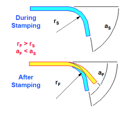
    spring1

    Figure 1.  Elastic Springback  (the change in the angle from start to finish of the forming process)

                      (r = radius, a = angle, s = start, f = finish)      

    spring2
     Figure 2.  Strain and Stress Behaviour During the Forming Process