Gradient Background Image
 

Tech Matters

TECH MATTERSbailey Metal Processing Limited - Products


  • Yield Point Elongation (YPE) – Pros and Cons

    by Esther Mar | Jan 21, 2020
    Yield Point Elongation (YPE) – Pros and Cons

    Yield Point Elongation is a characteristic that has a significant effect on the usability of steel. To recap what is stated in the article on Tensile Testing, in a reference to the Engineering Stress-Strain curve, the Yield Point is the first stress, less than the maximum obtainable stress, at which an increase in strain occurs without an increase in stress. Such behaviour is only common to certain materials. These materials are said to exhibit a Yield Point Elongation (YPE) as seen in the schematic on the left.

    ype1
    The presence of a YPE can be detrimental in that it can result in conditions such as coil breaks, edge breaks, fluting, stretcher strain, and reel kinks/creases, which may be aesthetically undesirable. Sometimes the conditions are severe enough to affect flatness as well.
     
    Coil Breaks and Edge Breaks can be incoming or can occur during customer processing depending on the history of the material. Fluting and Stretcher Strain occurs during forming. Reel Kinks are transverse ridges, or “breaks”, on successive inner wraps of a coil. These are caused by the start of the coiling process. Example photographs follow.
     
    Where such conditions are objectionable the supplier needs to know so as to provide appropriate material. The presence of YPE is affected by chemical composition (there are grades that don’t exhibit a YPE) and by mill processing (skin passing/temper rolling). The latter eliminates the YPE in addition to improving the surface and slightly reducing thickness variation. The effect is temporary, though, as with time the product undergoes a phenomenon called “aging” and the YPE returns.
     
    YPE in steel does, however, have a beneficial effect in certain applications, specifically in roll forming. Similarly, steel with a pronounced YPE shows less springback than steel with no YPE. Generally speaking steel with a YPE is highly formable.
     
    Coil Breaks
    ype2

    Edge Breaks
    ype3

    Fluting
    ype4

     
    Stretcher Strain
    ype5
     ype6
     
    Reel Kinks
    ype7 ype8

     
    (A kink is shown in the 3 o’clock position in the photo on the left. The photo on the right shows a partially stoned sample.)
  • Young’s Modulus (Elastic Modulus, Modulus of Elasticity)

    by Esther Mar | Mar 28, 2019

    In the article on Tensile Testing there is brief description of Young’s Modulus (also called the Elastic Modulus or Modulus of Elasticity).  Every now and again a question is raised as to whether it is possible to change this material characteristic, usually because designers are looking for more stiffness in a particular structure.  Hence, a discussion on Young’s Modulus is provided.

    When a metal is subjected to load in a tension test, there is an initial range of loading in which no permanent deformation of the specimen occurs, i.e. if the load is removed at any value within this range, the specimen will return completely to its original dimensions.  This is known as the elastic range.  The data obtained from the tension test is generally plotted as a stress-strain curve.  Within the elastic range of loading the strain produced is directly proportional to the applied stress.  The law of proportionality between stress and strain in the elastic range is known as Hooke’s Law.  The Young’s Modulus is the ratio between the stress that is applied (tensile or compressive) and the elastic strain that results, i.e. it is the slope of the elastic portion of the stress-strain curve and is expressed in units of stress (psi).  The higher the modulus, the more stress is needed to create the same amount of strain, i.e. the higher the modulus the higher the stiffness or rigidity of the material.  Since Young’s Modulus is needed, in conjunction with thickness, for calculating deflection of beams and other members, it is an important design value. 

    Young’s Modulus is determined by the binding forces between atoms.  Since these forces cannot be changed without changing the basic nature of the material, it follows that the Young’s Modulus is one of the most structure-insensitive of the mechanical properties.  It is only slightly affected by alloying additions, heat treatment, cold work, or, in the case of steel, by relatively exotic microstructures such as dual phase.  The tensile Young’s Modulus of ferritic steels is close to 30,000,000 psi at room temperature.  The tensile Young’s Modulus of austenitic stainless steels is about 28,000,000 psi at room temperature. Within each material class there are very small differences. Increasing the temperature decreases the Young’s Modulus.  It decreases linearly to somewhere in the order of 1000oF, depending on material class, and then begins to drop rapidly.

    Because the stress-strain relationship of many materials does not conform to Hooke’s Law throughout the elastic range, there are several methods of defining the Young’s Modulus as a straight line relationship using an approximation such as an initial tangent modulus, a tangent modulus at any stress, a secant modulus between the origin and any stress, and a chord modulus between any two stresses.  An ASTM standard exists for test methods.

    youngmodulus


    Although Young’s Modulus is a characteristic of the stress-strain curve, its precise determination using static methods (deflection under load increments in a tension test) requires regard for numerous variables, including the accuracy and the precision of the apparatus used to measure stress and strain, characteristics of the test specimen (such as grain orientation relative to the direction of stress, grain size, residual stress, previous strain history, dimensions and eccentricity), testing conditions (such as alignment of the specimen, speed of testing, temperature, and temperature variations) and interpretation of the test data. Following the ASTM standard ensures far more accurate results than taking the number off a routine stress-strain curve.  However, the more accurate methods are dynamic in nature and are based in induced mechanical vibration or ultrasonic pulses where the mode and period of vibration of a metal specimen are obtained and analyzed.


  • Thickness Expectations in Sheet Products

    by Esther Mar | Jun 22, 2018

    There is a book I am hoping to locate and read called “Ribbon of Fire” by Jonathan Aylen and Ruggero Ranieri.  Abstracts say that it reviews economic and technological developments showing how the wide hot strip mill evolved in the USA from narrow (3” max) hot strip mills rolling ‘hoop’ in the 19th century, through 4” mills rolling ‘skelp’ to 7” wide mills rolling 100’ lengths by 1890.  Widths and lengths rolled slowly progressed - 24” wide and 500 – 1000’ long - and then a breakthrough was made in 1923 by an engineer at Armco and in January 1924 the first 36” wide hot strip was rolled in the multi stand mill in the Middletown Works, in Ohio.  This was rapidly followed by an improved 36” mill at the Columbia Steel Co. at Butler Pennsylvania, which soon was widened to 48”.  The main innovation of this mill was a four high finishing stand using a small diameter work roll supported by a larger back up roll, this enabling greater reduction between passes.  It is from this mill design that all future wide hot strip mills developed. 

    From the technology of the four high mill stand stems the understanding of gauge performance of sheet products.  I say “sheet products” because as the product range of these mills increased, governing bodies differentiated between “sheet” and “strip”, the latter being rolled in narrow mills.  For example, ASTM A568 (Steel, Sheet, Carbon, Structural and High-Strength, Low-Alloy, Hot-Rolled and Cold-Rolled, General Requirement for) classifies “hot rolled strip” as material with mill edges 12” and less in width.  “Hot rolled sheet” is further reduced in wide cold reduction mills to produce “cold rolled sheet”.  But “cold rolled strip” is rolled in “strip mills” that are narrow cold mills.  The raw material for it is generally “hot rolled sheet” that has been pickled and slit into narrow widths.  The end product has thickness variation which is less than sheet mill industry tolerances and is often produced to custom characteristics.

    The following text deals with thickness variation in hot rolled and cold rolled sheet but uses the term “strip” because it is the commonly used terminology in the trade.

    The process of creating a finished flat rolled product from a slab consists of several stages.  These stages in a typical hot rolling mill are: reheating the slab, roughing, finishing, measuring, cooling, and coiling. As the hot steel travels through the process its thickness is successively reduced in the various mill stands. 

     thickness1

    The finishing process gives the strip its final dimensions.  The strip thickness (and flatness) is measured in real time by X-Ray gauges at the exit of the finishing stands.  Measuring the final dimensions of the strip is critical for the mill controllers as they adjust the mill parameters in real time with feedback from the gauges to minimize variation in thickness (and shape).

    The concept of the mill stand mentioned at the end of the first paragraph is shown below. A stand like this is several stories high. It is composed of  a set of work rolls between which the strip passes, a set of backup rolls, which are bigger, and actuators to control the gap and the bending of the rolls, all supported by a frame.
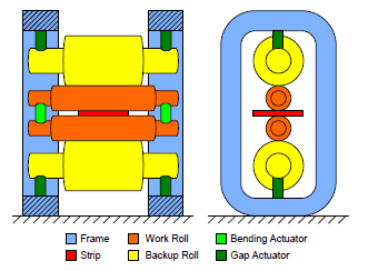
    thickness2

    Rolls consist of two parts:  barrel and neck.  The barrel is the part of the roll that comes into contact with the strip or another roll.  The neck is the thinner portion of the roll, part of which rests in a bearing.  The bearing is held by a chock which is connected to the stand frame.  As the hot strip travels through the stands there is force on the rolls which causes their deflection and resulting strip deformation.  This force, as well as other factors (including roll thermal profile, roll wear, strip width) affects the cross width dimensions of the strip.  The resulting cross section of the strip looks as in the schematic below.
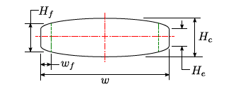
    thickness3

    Most mills refer to the overall cross width configuration as the “profile” which is composed of the edge drop off, or feather, and the crown.  The crown is the difference in thickness between the thickness at the centre of the strip and the thickness at the end of the edge drop off, or feather (usually about 2” in from the mill edge). 

    The profile of the strip is generally consistent from the lead end of the coil to the trail end of the coil although it can vary towards the coil ends.  Separately, there are methods in modern hot strip mills that are used to control the shape of the strip (both in terms of flatness and crown).  These include:  roll bending, roll shifting, and inflating roll (variable crown roll).

    When hot rolled strip is cold reduced the aspect ratio of the hot strip profile is maintained but the magnitude is proportionally smaller in the cold rolled product.

    The following table from ASTM A568/A568M – 13a provides the tolerances for hot rolled sheet steel.  The tolerances include variation along the coil length and across the coil width.  The variation attributable to the profile can be in the order of 1 – 5% of the average thickness depending on a variety of factors.
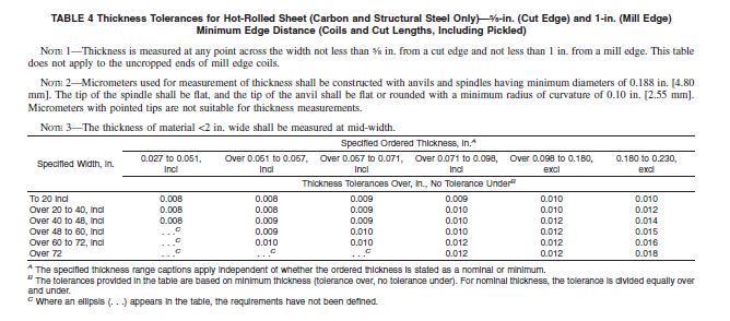
    thickness4

  • Galvanneal and Galvanize – Similarities and Differences

    by Esther Mar | Feb 21, 2018

    Hot –dip galvanneal and hot-dip galvanize can both be produced on the same continuous coating line.  The fundamental steps in the process are:

    • Uncoiling a steel coil (usually cold rolled full hard)
    Preparing/cleaning the incoming steel strip
    Annealing
    Applying zinc coating (with a small aluminum level that is lower in galvanneal than galvanize)
    Wiping off excess coating
             ○
    Reheating (in the case of galvanneal production)
    Cooling the strip
    Temper rolling and/or tension leveling
    Applying a surface treatment (e.g. passivation, oil)
    Recoiling

    Coating differences

    • Galvanize has a zinc coating with a very thin iron/aluminum/zinc bonding layer.
    • In manufacturing galvanneal, the objective is to convert the zinc coating to a zinc-iron alloy with a bulk composition of approximately 90% zinc and 10% iron.This is done in a Galvanneal Furnace by reheating the strip in a controlled fashion to between 500 – 600oC, for a few seconds, soon after the wiping knives.The iron diffuses out of the steel into the zinc coating producing 3 layers of inter-metallic phases called Zeta, Delta and Gamma each having an increasing iron content, with Gamma being closest to the steel surface.

    Visual differences

    • Galvanize has a shiny metallic appearance.
    • Galvanneal has a dull gray matte appearance.

    Performance differences

    • Weldability
      • Zinc-iron alloy coatings generally have better spot welding characteristics than pure zinc coatings.The coating has higher electrical resistance, hardness and melting point than a pure zinc coating, allowing welds to be obtained with lower currents with longer electrode life.
    • Paintability
      • Better paint adhesion is obtained with a galvanneal coating because the paint is mechanically locked into its porous surface.
    • Formability
      • Galvanize coating is quite soft and is easily scratched.In fact its ductility allows it to act almost as a lubricant in a forming die.By comparison a galvanneal coating is very hard and therefore not as easily scratched when handling.Galvanneal coating can also be stretch formed and drawn under specific conditions and many deep drawn automotive parts are produced from a galvannealed product. The galvanize coating may gall on deformation whereas the galvanneal coating may powder.
    • Adherence
      • Both products offer excellent adhesion to the steel substrate.
    • Corrosion Performance
      • The corrosion performance of galvanized steel is directly related to the thickness of the coating.
      • The corrosion performance of galvannealed steel is not normally compared to galvanized steel because most of the applications are painted after fabricating.Coating thickness also plays a part in the corrosion protection of galvanneal.

    In summary whether to use galvanize or galvanneal depends on the demands of the specific application.

    Galvanized Steel

    Galvanized Steel

    Galvannealed Steel
    Galvannealed Steel

  • Inclusion Control and Inclusion Shape Control in Steel

    by Esther Mar | Jan 09, 2018

    The following is a quotation from the 1948 edition of the ASM Metals Handbook:

    “Any specimen of steel when examined closely enough will reveal the presence of particles of material incongruent with the metal lattice and demonstrating either definite nonmetallic or quasi-metallic properties.  Some of these are obviously of foreign origin and are entrained particles of refractory, slag and the like, that have been entrapped by the freezing steel.  These are called exogenous, adventitious or accidental inclusions.  Others just as evidently have been precipitated from the liquid or solid metal as a result of chemical reactions or of solubility changes caused by varying temperature.  Such inclusions are known as indigenous, natural, or native inclusions and must be considered an integral part of the heterogeneous and complex material known as steel.  They are as much a part of steel as seeds are part of a fruit.

    inclusion1

    These days, along with the popularity of seedless grapes, many steel customers have requirements for steel with a minimum volume fraction of inclusions and length of inclusions.  Various properties are adversely affected by inclusions; including impact properties, hot fatigue strength, hot workability, and formability.  Especially in forming applications manganese sulphide “stringer” inclusions are detrimental to edge stretching.  For such applications steel with “inclusion control” is often specified.  It is important to note, however, that this term is not equivalent to “inclusion shape control”.  The former requires the steel producer to lower the Sulphur content of the steel whereas the latter requires the steel producer to modify the shape of sulphide inclusions so that they are less damaging.  Inclusion control is accomplished through various practices in the refining and continuous casting operations.  Inclusion shape control is commonly achieved by calcium treatment.

    inclusion2

    Calcium is generally added to steel in a stabilized form such as calcium silicon, delivered via cored wire, using a wire injection system.  This is normally done in the ladle after trim additions and argon rinsing.  Calcium is a powerful deoxidizer and desulphurizer and thus has two beneficial effects.  The first is that it reduces the total number of inclusion remaining in the steel and the second is that it modifies the shape of the remaining inclusions into more globular ones that are less detrimental to the properties of the final product.

    As steelmaking quality has improved “inclusion controlled” steel has become cleaner and often just specifying in this manner is sufficient for many applications.  An example of such a specification is ASTM A1011 HSLAS-F (where the “F” designates improved formability).  In applications where “inclusion shape control” is known to be required special care must be taken to specify this even where the governing standard does not refer to it.